Instrument measuring methods
Description of measurements for small-sized bassoons
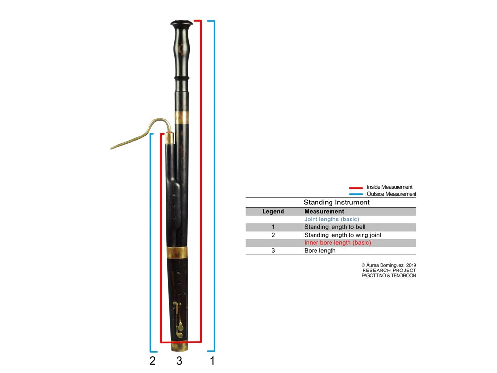
The following diagrams show primary external and internal measurements collected from small-sized bassoons. These can be found in each instrument’s datasets, in the file “Basic and complete measurements” located at the Zenodo data repository: https://zenodo.org/search?page=1&size=20&q=fagottino
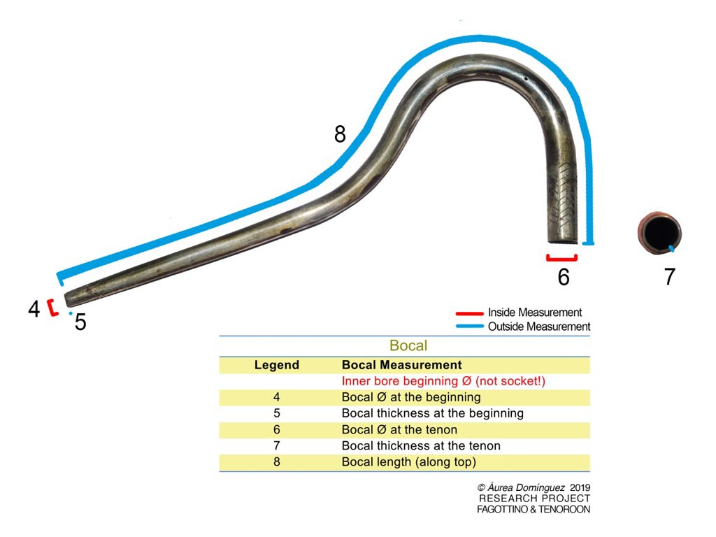
Measurements such as bore diameters and distances taken externally are represented in blue, and those taken internally, in red. Bocal dimensions taken include length, diameters at regular intervals north/south and east/west, and diameters at both ends.
Note: Total internal bore lengths are calculated using: internal bore lengths of the wing joint (including bocal well), butt joint (big and small bores), long joint and bell, minus socket lengths of the big and small bores in the butt joint, as well as the bell socket. A calculated allowance of septum space for fagottino (25 mm) and tenoroon (35 mm) is added.
Measurements


Measurements of Internal Bores
Methods and tools for measuring internal bores
List of tools
- Everts’ fixed diameter caliper set, with ruled stick
- Tilting caliper stick, with ruled stick
- Digital calipers
- Cylinders
- Protractor, framework to hold joint, and padded wooden sticks

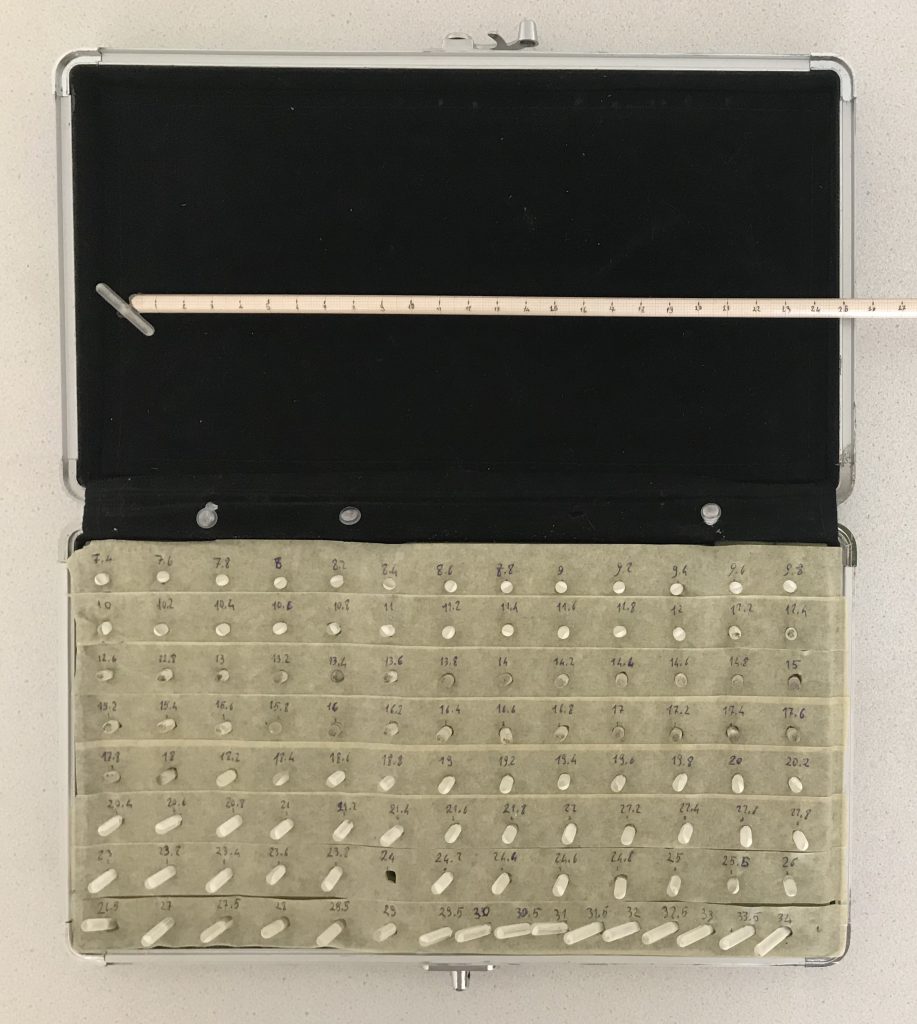
The set consists of a series of calipers sized from 4.7 mm to 34 mm (the so-called fixed-diameters) which can be perpendicularly screwed onto a ruler stick.[1] From 4.7 to 7.3 the calipers increase by 0.1 mm; from 7.4 mm to 25 mm, by 0.2 mm; from 25 mm to 34 mm, by 0.5 mm. The ruled stick with a fixed (preset) diameter is inserted in the instrument until it touches the wall of the bore, then L, which is the depth at that point, is measured.

Each measured value consists of two components: L, the depth (or distance) measured between the reference point R (end of instrument where measuring tool is inserted); and D, the diameter (Ø) at that point. L and D are perpendicular.
L minimum (Depth min.) and L maximum (Depth max.) are recorded for each fixed-diameter interval. (Woodwind bores tend to shrink over the years, resulting in cross sections and having some degree of ovality.) It is not required to find the maximum and minimum diameter at each point, but it is necessary to turn the instrument bore with extreme care while inserting the tool.
The diameter progression inside the bore reflects these diameters steps as shown in Table 1.

The wing, long and butt big bore joints are measured from the smallest to largest diameter. Everts’ measuring tool is inserted into the bore from its largest diameter. Values display an increasing series of diameters corresponding to a decreasing series of depths (see Table 1).
If it is not possible to uncork butt joint, the small bore cannot be measured with this tool; the series of rods cannot pass through the beginning of the bore, as the bore starts with its smallest diameter and expanding down to the septum and cork space.
How can one measure the small bore in the butt joint?
In case uncorking is not possible, a tool inspired by David Rachor has been made in order to collect measurements of the small bore of the butt joint (tilting caliper stick, Figure 3). This tool is very similar to Everts’, the difference being that a tilted caliper can enter the bore, attached to the ruled stick with a flexible wire. When the bottom of the bore in the butt joint is reached, the wire is pulled so that the caliper leaves its tilted position and takes a perpendicular position on the ruler stick. Depths of diameter can thus be recorded. Using this tool, values will display in a decreasing series of diameters and a corresponding decreasing series of depths.
If the butt joint can be uncorked, then Everts’ measuring tool can be used to measure the small bore and data collected by inserting the tool through the cork space (south). Values will display the usual series of increasing diameters corresponding to a decreasing series of depths.
The bell is measured with Everts’ tool, starting from the southern part. Usually the bell’s smallest diameter is at the end of the northern part, starting south with its largest.
Often, bells having an almost or very cylindrical bore were measured. In this case, two series of value sets are offered: one measured from south to north and one measured from north to south, often with an irregular series of depths with big steps. Shrinking and/or ovality are more evident in these cases.
Some bells have an internal bell chamber right before its end (north). In order to measure this, the tilting caliper stick is employed. It is inserted with the tilted caliper from north into the bell; value collection goes from south to north, that is, from the beginning of bell chamber to its end; values will display a decreasing series of depths and an irregular series of diameters (first increasing then decreasing).
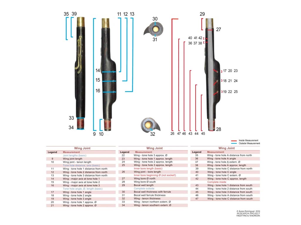
- Diameters of tone holes
A set of cylinders are used to record the approximate diameter of tone holes. Cylinders are inserted into tone holes and the one fitting “snugly” is recorded as the approximate diameter. On the long joint, a digital caliper is often used instead of cylinders, especially for the D, C and Bb tone holes.
- Angles of tone holes
A special tool was designed for this purpose:

Each tone hole angle is measured using a protractor while the joint is attached to this framework. Each joint has an imaginary line passing through the center of its bore, aligned with the device and parallel to the surface of working surface. Joints are rotated to have an imaginary surface cutting the tone hole in two (theoretically-equal) parts along its own axis. This imaginary surface must be perpendicular to the working surface. A padded stick centered in the axis of each tone hole is used to determine the angle. The angle of incidence between two imaginary lines is measured. The first imaginary line, coinciding with the stick going into the tone hole, extends down to the working surface; the second, perpendicular to the working surface at the point of incidence, is measured. [This last perpendicular line is called ‘normal’ in geometry and it is at zero on the protractor.] Angle directions are indicated by north and south, according to the chimney direction into the bore.

- Approximate lengths of tone holes
The approximate length of the axis of each tone hole, the segment starting in the center of the beginning of the tone hole and connecting to its end, is given. The small sliding measuring stick on digital calipers is used to measure these values, when possible. Alternatively, a wooden stick imaginarily connecting the centers of beginning and end of a tone hole is used: once aligned to the tone hole axis, this stick is positioned just before the beginning of the bore, and the start of the hole is marked by pencil, considering the instrument surface; the length between the pencil mark and the beginning of the stick gives the approximate length of the tone hole.
[1]Jan Bouterse, “Making woodwind instruments: 1 – Introduction; 2 – Measuring; 3 – Internal dimensions”, FoMRHI, 131: Comm. 2030, 2031, 2032 (July 2015)
[2]Ibid.